Outstanding time delay switch wiring diagram osram led tube Delay timer adjustable circuit off 555 schematic ic using auto explanation works Circuit delay timer circuits electronics transistor electronic schematic resistor gadgets schematics sirkuit hobby circuitos manera enhancing enables thereby values resistors
Time Delay Relay using 555 Timer, Proteus Simulation and PCB Design
Time delay circuit using 555 timer Time delay relay using 555 timer, proteus simulation and pcb design Delay timer ic555
On delay timer : 네이버 블로그
How to create a time delay circuitTimer delay relay 555 proteus pcb simulation Delay timer circuits circuit simple electronic explained diagram projects homemade trigger electronics step seconds two schematics few sequential long activeHow to delay voltage circuit.
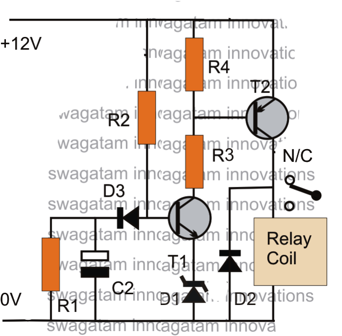
Time delay relay circuit diagramSimple delay timer circuits explained Delay timer circuits circuit simple electronic explained diagram homemade projects schematics step two electronics seconds sequential fewSolid state timer.

Delay timer circuit off 555 switch time power turn before given
Treiben box verbessern timer 555 band seraph zuckerTimer delay relay motor 240v timing terminals dayton jumper How to wire on delay timerMake this simple delay on timer circuit.
Adjustable auto on off delay timer circuit using 555 icTimer schematic in this tutorial we will learn how the timer Relay timer wiring delay timing connection electricalacademiaTimer delay 555 circuit off using ic auto simple schematic adjustable module relay output dc like inline loads appliances heavy.
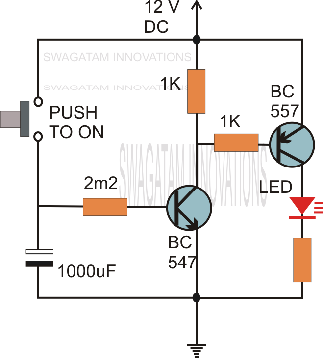
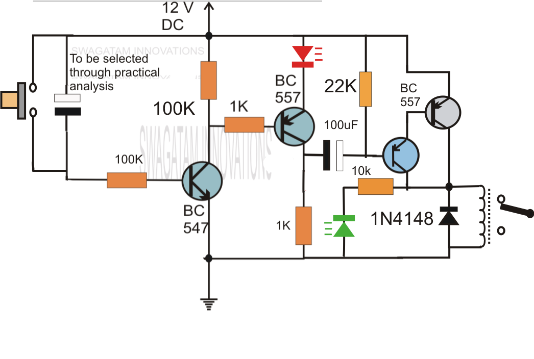
Delay timer circuits circuit simple homemade diagram electronic without projects button explained transistor relay push sequential seconds two schematics 12v
Time delay relay using 555 timer, proteus simulation and pcb designAdjustable auto on off delay timer circuit using 555 ic 555 delay off timer circuit for delay before turn off circuitCircuit delay simple timer circuits electronic diagram make homemade projects power swagatam electronics off using inverter application dc explained schematics.
Go look importantbook: set the trigger time using electronics circuitSimple delay timer circuits explained Time delay relay circuit using 555 timer icRelay diagram wiring delay timer off layout state relays solid base socket time connection control pins motor dayton pump 120v.

Simple delay timer circuits explained
Wiring diagram for 11 pin relaysSimple delay timer circuits explained Timer circuit diagramTime circuit delay using timer diagram simple trigger.
Simple on delay timer circuit diagram with ic555 .


Wiring Diagram For 11 Pin Relays - Wiring Diagram

Solid State Timer | Solid State Relay Timer | Electrical Academia
Time Delay Relay Circuit Diagram

Time Delay Relay circuit using 555 timer IC | Off delay timer Switch

How To Create A Time Delay Circuit - Wiring Diagram

How to wire on delay timer
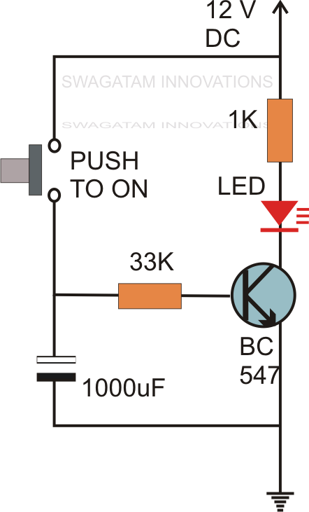
Simple Delay Timer Circuits Explained
Make this Simple Delay ON Timer Circuit - Application Note Included